Test Description of Dayangmubei River Bridge
1.1 Summary
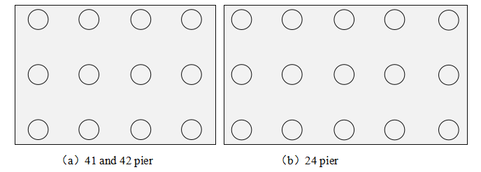
The project is the dayangmubei River Bridge of mjzqsg-3 bid section of the new Mudanjiang Jiamusi railway pre station project, which is located in Linkou County,Mudanjiang City, Heilongjiang Province. At present, the foundation piles and superstructure (bearing platform, pier and abutment, railway bridge, etc.) of Dayangmubei River Bridge have been completed. There are 12 piles under the bearing platforms of 41 and 42 piers and 15 piles under the bearing platforms of 24 piers and abutments. In the early stage, the client has carried out low strain test on the foundation pile before the construction of the superstructure.
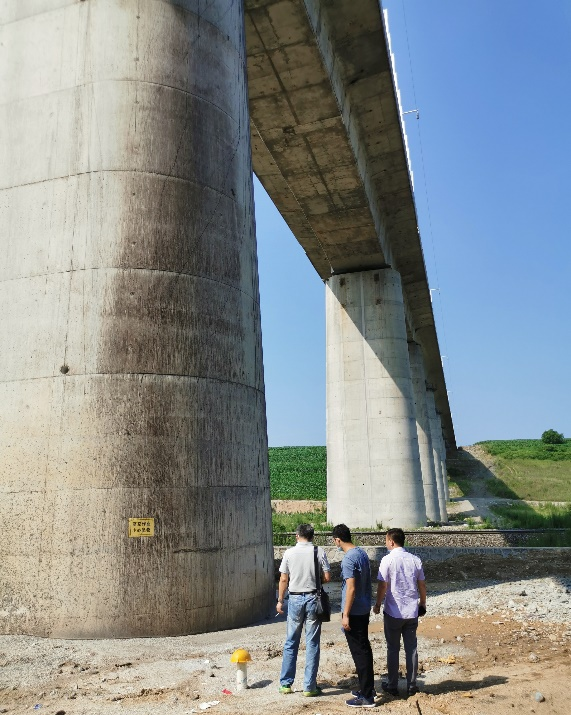 (c)Actual site conditions
Figure 1 distribution diagram of foundation piles under bearing platform
There are 6 piles in the test object, distributed in 3 different piers and abutments. They are: 24#1, 24#4 of 24 pier and abutment,41#1, 41#4 of 41 pier and abutment, 42#9 of 42 pier and abutment, 42#10.The 6 piles are all located under the bearing platform, and the superstructure such as the bearing platform and the pier above has been completed.
According to the relevant data provided by the entrusting party and in combination with the actual situation on site, the basic information of the above six piles is summarized as follows:
1.3 Test purpose
The main purpose of testing the above six piles is to retest and verify the pile length of the foundation pile under the bearing platform after the construction of the superstructure.
1.4 Test method
The main test basis is technical Standard for Testing of Existing Building Foundation (JGJ/t422-2018). The following two methods are used for field test:
2. The magnetic pile method uses RSM-RLT(C)Reinforcement Length tester
1.5 Test process
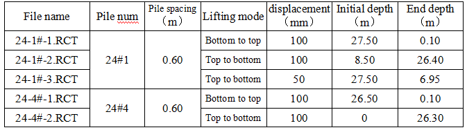
① Reinforcement Length test
RSM-RLT Reinforcement Length tester is used for relevant tests, each pile is tested by two lifting methods, i.e. from bottom to top and from top to bottom. Each test method is tested for many times, and the displacement of measuring points is mainly 10cm and 20cm.
Pile No.:42#10,42#9,41#1,41#4,24#1,24#4,Specific data are shown below:
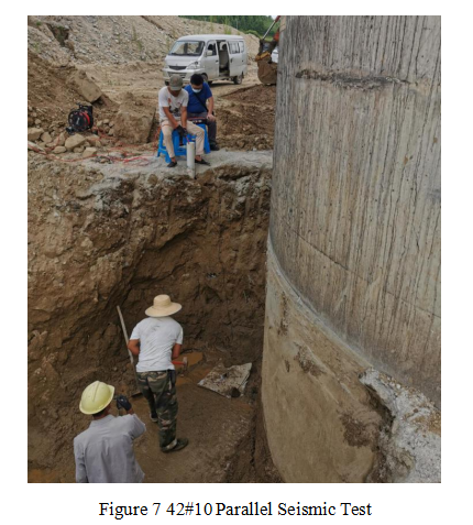
② Parallel Seismic Test
RSM-PST Parallel Seismic Tester is used for relevant tests. Before the test, the soil layer above the cushion cap shall be excavated to expose the surface of the cushion cap, and the trigger accelerometer shall be installed on the surface of the cushion cap and fixed with mud. The specification of the vibrating hammer is 12 pounds, and the displacement of the measuring point is 20cm.
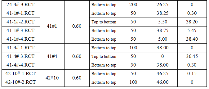
① Reinforcement Length test(retest)
According to the analysis of the reinforcement cage length test on July 18, 2020, the piles in question during the test were retested. During the retest, the shift distance of measuring points is increased, and the shift distance of measuring points is mainly 10cm and 5cm.
Retest pile num:42#10,41#1,41#4,24#1,24#4.Specific data are shown below:
② Parallel Seismic Test
Continue the test method of the first day and test the remaining 4 piles.
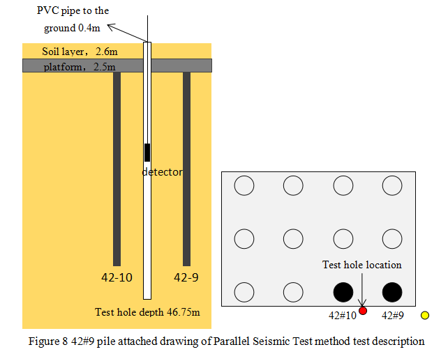
Description on the test process of No. 42\9 pile: when the test of No. 42\9 pile was carried out, a total of 3 tests were carried out.
i. Continuing the previous test method, after the soil layer is excavated to the surface of the platform, the trigger accelerometer is installed on the surface of the platform. The specification of the excitation hammer is 12 pounds, the displacement of the measuring point is 20cm, and the test depth range is 45m-33.8m. During the test, the test curve is abnormal during the probe lifting process. The preliminary judgment may be that the test hole is far from the pile body (it is estimated that it is more than 2m on site). When the signal generated by the shock hammer is transmitted to the test hole through the pile body, the signal is disordered, and the collected signal is obviously abnormal, so it is impossible to conduct effective analysis. Then lift the probe out to end the first test. (the corresponding data file name of this test is 42-9.pst)
ii. On the basis of the first test, adjust the hammering point, and test again in the same test hole. At the beginning of the test, 20cm measuring point shift was used for sampling at the bottom of the hole (45m-40m), and it was found that the test situation had not been significantly improved. Subsequently, the shift distance of measuring points was adjusted to 1m, and some measuring points (40m-27m) were tested. Except that the signals measured at 35m were valid signals, the signals of other measuring points were still disordered. Finally, the shift distance of the measuring point was adjusted to 2m, and the remaining range (35m-1m) was tested. Except that the data of a few test sections (23m-15m) were normal, the signals of other parts were abnormal. This test still failed to measure the effective signal (the name of this test curve file corresponds to 42-9-2.pst)
iii. According to the analysis of the previous two tests, it may be that the test hole is too far away from the pile body, and the PVC pipe in the test hole may have a gap with the surrounding soil layer, which further weakens the signal of stress wave and leads to abnormal test curve. In this case, it is decided to test the 42#10 pile first, and the test effect of the 42#10 pile is good.
After the completion of pile 42#10 test, considering that the test hole of pile 42#10 is also not far from pile 42#9, and the test effect of this test hole is good, it is decided to use the test hole of pile 42#10 to test pile 42#9. During the test, the position of the trigger accelerometer and the excitation point is adjusted to the platform directly above the 42#9 pile. The collected signal is stable during the test, and the test effect is good. It shows that the reason for the abnormality of the first two tests is that the test hole position is unqualified. (the name of this test curve file corresponds to 42-9-3.pst)
Attachment: test curve and analysis results


