Crosshole sonic logging refers to the method of transmitting and receiving sound waves between the embedded acoustic tubes, and testing the integrity of the pile body by actually measuring the relative changes of acoustic parameters such as sound time, frequency and amplitude attenuation of the sound waves propagating in the concrete.
sonic logging method for testing piles
The sonic logging has become an important means of integrity testing of concrete cast-in-place piles (especially large-diameter cast-in-place piles), and has been widely used in many fields of engineering construction such as industrial and civil buildings, water conservancy and electricity, railways, highways and ports.
Measurement of Underground Diaphragm Wall by sonic logging
Principle
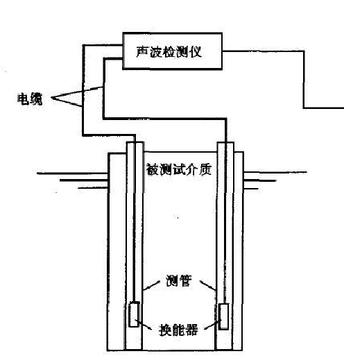
After the foundation pile is used to make holes and before the concrete is poured, embed a number of sonic logging pipes in the pile as the channels for the acoustic wave transmitting and receiving transducers. Start the test several days after the pile body concrete is poured. Apply the ultrasonic pile integrity tester in the longitudinal direction along the pile at certain intervals to detect the parameters of the acoustic waves passing through each cross section of the pile body. Then, process, analyze and judge the test data, and determine the location, range and extent of the pile concrete defects, thereby inferring the pile concrete continuity, integrity and evenness, and assessing the pile integrity level.
CSL principle
Testing method
According to the different arrangements of ultrasonic transducer channels in the pile body, there are three methods for ultrasonic transmission method pile integrity testing:
1. Single hole transmission method in pile
2—Transmitter
3—Receive transducer
4—CSL tester
In some special cases, only one hole can be used for testing. For example, after drilling the core, we need to further understand the quality of the concrete around the core sample. As a supplementary method for core drilling, the single-hole detection method can be used at this time. At this time, the transducer is placed in a hole, and the transducers are isolated with sound insulating materials (or a dedicated one-shot double-receive transducer is used). The sound wave starts from the transmitting transducer and enters the concrete surface of the hole wall through the coupling water, and slides along the concrete surface for a distance, and then reaches the two receiving transducers respectively through the coupling water, so as to measure the sound wave propagation along the hole wall concrete. various acoustic parameters.
When the single-hole transmission method is used for detection, since the sound propagation path is much more complicated than the cross-hole method, signal analysis technology must be used. When there is a steel casing in the hole, this method cannot be used because the steel pipe affects the detour of the sound wave in the hole wall concrete.
For single-hole testing, the effective detection range is generally considered to be about one wavelength (8-10cm).
2. Outside the pile single hole transmission method
1—Sonic Logging Pipe
2—Transmitter
3—Receive transducer
4—CSL tester
When the superstructure of the pile has been constructed or there is no transducer channel in the pile, a hole can be drilled in the soil layer outside the pile close to the pile edge as a detection channel. Since the sound wave attenuates quickly in the soil, the outer hole of the pile should be as close to the pile body as possible. When testing, place a plane transducer with a large transmitting power on the top surface of the pile, the receiving transducer is slowly lowered from top to bottom from the outer hole of the pile, and the sound wave propagates down the concrete of the pile body, and passes through the pile and the pile. The soil layer between the holes enters the receiving transducer through the coupling water in the hole, and the acoustic parameters of the transmitted sound wave are measured point by point. When encountering broken piles or interlayers, the sound at the following points increases significantly, and the wave amplitude drops sharply, which is the basis for judgment, as shown above. This method is limited by the transmission power of the instrument, the measurable pile length is very limited, and only defects such as interlayer, broken pile, and diameter reduction can be judged. In addition, the geometry of the pile body section of the cast-in-place pile is often irregular, which brings difficulties to testing and analysis.
This method is not mentioned in the specification and is not recommended.
3. In-pile cross-hole transmission method
According to the change of the relative height of the two transducers, the cross-hole method in the pile can be divided into flat, oblique, cross-oblique, sector scanning measurement, etc., which can be flexibly used in detection according to actual needs.
When the core drilling method is used to test the integrity of the large diameter cast-in-place pile, there may be more than two core holes. If we need to know more about the concrete quality of the pile body between the two boreholes, the core hole can also be used as the channel of the transmitting and receiving transducers for cross-hole transmission detection.
The application of three methods of cross-hole transmission method in piles:
In the field CSL testing process, the first step is to use the flat measurement method to conduct a general survey of each detection section of the whole pile to find out the measurement points with abnormal acoustic parameters.
Then, the measurement points with abnormal acoustic parameters are further detected by fine measurement methods such as encrypted flat measurement test, oblique measurement or sector scan measurement, so that on the one hand, the census results can be verified, and on the other hand, the scope of abnormal parts can be further determined, which is the pile body. The determination of the integrity category provides a reliable basis.
1. Flat test
Synchronous lifting and lowering at the same elevation to complete the whole pile testing.
1—Sonic Logging Pipe
2—Transmitter
3—Receive transducer
4—CSL tester
2. Oblique test
The transmitting transducer and the receiving transducer are placed at different heights to be raised synchronously, and the measurement lines with abnormal acoustic parameters of the two tests are analyzed to further determine the defect range more accurately.
3. Fan test
One transducer is fixed at a certain elevation, the other transducer moves point by point, and the survey line is distributed in a fan shape. It should be noted that the distance measurement of each measuring point in the sector measurement is different. Although the wave speed can be converted and compared with each other, the amplitude measurement value is not comparable with each other (the wave amplitude is not only related to the distance measurement, but also related to the azimuth angle. And it is not a linear change), and it can only be found whether the survey line encounters defects according to the sudden change of the measured value of the adjacent measuring points.


