1. Background
With the infrastructure construction of China “One Belt One Road”, a large number of large-scale facilities and buildings (structures) are under construction and operation, with land, sea and air passages and information highways as the framework, and major projects such as railways, ports, and pipe networks. A complex infrastructure network based on it is taking shape.
However, with the long-term operation of large-scale facilities, various deformations will occur due to the influence of itself or external factors. For example, when vehicles or trains pass by a bridge, vertical deflection deformation will occur; high towers will deform laterally due to the influence of external factors such as wind. Deformation is a key indicator that affects the safety and service life of large-scale facilities and buildings (structures). If there is no effective technical means to measure deformation, it is likely to cause engineering accidents and bring huge economic losses.
2. Traditional monitor methods
Traditional contact measurement methods mainly include connected tube static level, distributed optical fiber, dial indicator, pull-wire displacement meter, vibrating wire displacement meter, and magnetostrictive displacement meter. For the traditional contact measurement method, it takes a lot of manpower and material resources to arrange the sensor in the building or surface mount it on the outer surface of the building in advance. After the measurement is completed, it takes a lot of time to dismantle the sensor.
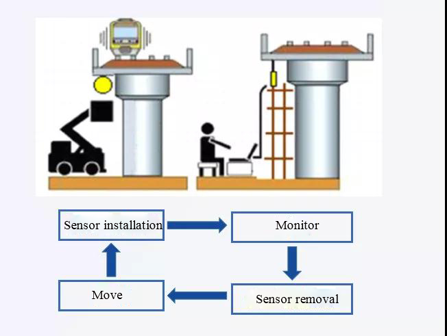
Flow chart of traditional contact measurement method
Shortcomings of traditional contact measurement methods
1. The installation and disassembly of the sensor is time-consuming and laborious;
2. The sensor is easily damaged during its life cycle;
3. A single sensor can usually only measure the one-dimensional deformation of a single point, and the monitoring frequency is low;
4. The deformation monitoring of a single building (structure) requires multiple sensors to be arranged, which is costly.
Traditional non-contact measurement methods are mainly total station, level, ultrasonic displacement monitoring, GPS/Beidou and radar displacement monitoring.
Shortcomings of traditional non-contact measurement methods
1. The total station has a large workload, a long measurement time, and human factors have a greater impact;
2. Ultrasonic measurement distance is short, the accuracy is low, and a reflective surface is required;
3. GNSS needs to be locally networked, the calculation accuracy is improved, and the single cost is higher;
5. The radar measurement accuracy is low and the cost is high.
3. Non-contact optical (image vision) measurement technology
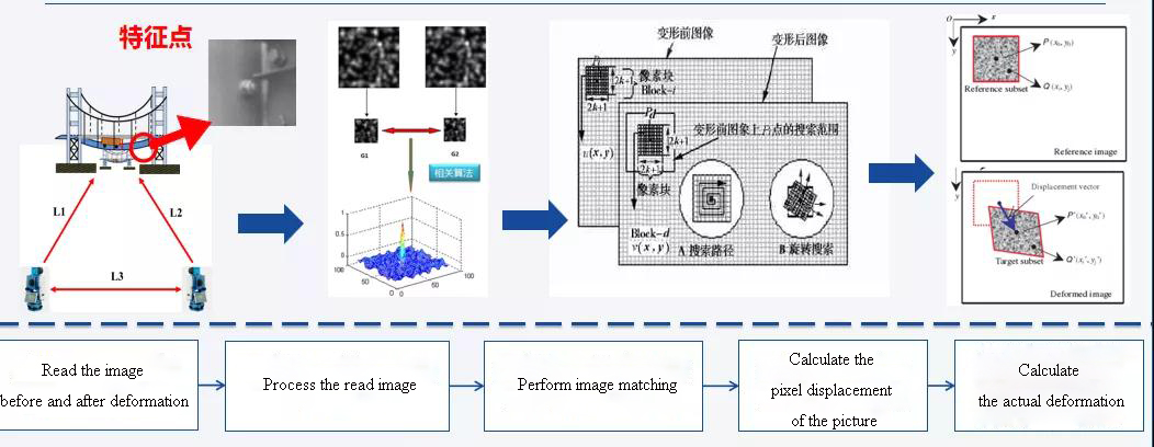
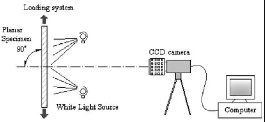
Image vision technology uses machines to replace human eyes for measurement and judgment. It is a comprehensive technology. A non-contact, full-field deformation digital image correlation method based on digital image processing and numerical calculation is used to measure the deformation of the surface of a large structure through two images before and after the deformation. This measurement method can realize long-distance, multi-point dynamic and static deformation detection of the measured object.
With the maturity of computer technology, the application of image vision is gradually shifting from indoor to outdoor large-scale structures (facilities), such as tunnels, slopes, bridges, and high towers.
Basic Principles of Image Vision
4. RSM-FBN(A) Product technology
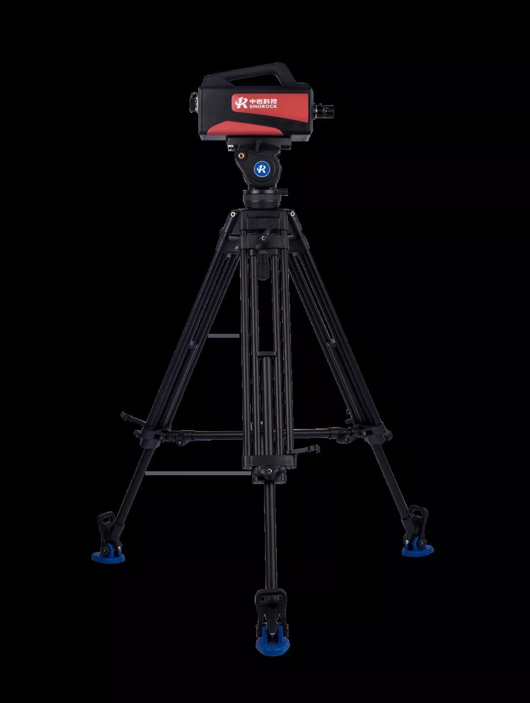
Through the most advanced image quality assessment algorithm, image quality enhancement algorithm and fast camera self-calibration technology, the RSM-FBN (A) non-contact bridge static and dynamic deflection tester can quickly measure the high-precision dynamic and static deflection, displacement and vibration at multiple points of such facilities as bridges, towers and hoisting machinery in real time through a main machine without any marks on site. The software system matched with the instrument has the functions of guided operation, automatic data recording, automatic calibration, intelligent point selection, real-time output, ultra-limit alarm and safety assessment. The instrument is designed integrally and equipped with military grade sensors and connectors, so it can be used intuitively, simply and conveniently on site.
5. Application
Test the dynamic/static displacement detection of such large facilities as bridges, towers and hoisting machinery, and can also be used for long-term monitoring of buildings, tunnels, dams and slopes.
6. Key technology
① Image acquisition
The visual image and inherent characteristics of the measured object are converted into a series of data that can be processed by a computer.
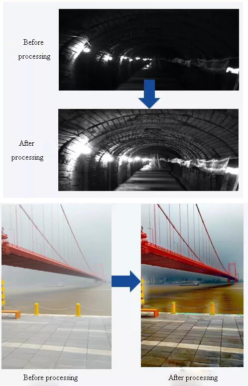
② High-resolution analysis of low-quality images
In response to the influence of factors such as illumination changes and haze under remote and large-scale measurement conditions in the field, a variety of fast image enhancement technologies have been developed to achieve high-resolution analysis of images under complex measurement conditions by improving image quality and breaking through the problem of low-quality image matching .
③ Quick self-calibration
In order to meet the deflection measurement requirements of large structures such as bridges, tunnels, high towers and hoisting machinery, active attitude sensing technology is used to develop camera self-calibration methods suitable for various complex working conditions, and the geometric constraint relationships of structural features in different measurement scenarios Or use the real-time posture information of the camera to realize rapid self-calibration of the camera.
④ High-precision target-free
In order to save engineering costs and improve measurement efficiency, this instrument combines image rapid correlation matching and positioning and saliency-based reliable feature extraction technology to develop a high-precision target-free measurement function suitable for various complex structures.
7. Applicable Standards
Highway Bridge Load Testing Procedures (JTG-T-J21-01-2015)
Technical Code for Monitoring of Building and Bridge Structures (GB50982-2014)
Code for Engineering Surveying of Urban Railway System (GB ∕ T 50308-2017)
Code for Engineering Surveying (GB 50026-2016)
8. Core Advantage
High precision
The instrument realizes the real-time calculation of 0.001mm-level high-precision displacement data through the unique fast self-calibration technology and by combination of attitude sensor, tangential and normal information of object surface.
High frequency
Synchronous high-frequency measurement at 300Hz on 40 points is realized by using professional-grade industrial camera and combination of special data processing and data transmission technology under the condition of ensuring measurement precision.
Large visual field
The instrument adopts a method of evaluating criterion based on image sharpness to remove the influence of such factors as sunlight/shadow and smog on image quality, adaptively improve and enhance the image quality, and meet the requirements of 1,000m long-distance measurement by combination of professional-grade lenses.
Multiply functions
The filtering function is perfect, through which the collected curves are pre-processed and post-processed. Multiple functions, such as impact coefficient, damping ratio, spectrum analysis and ultra-limit alarm are readily available. Images can be recorded first, and then processed and analyzed, which is convenient and quick;
9. Project case
Wuhan Changfeng Bridge
01Project Overview
Changfeng Bridge is a super large mid-through concrete-filled steel tube tied arch bridge spanning the Han River on the west section of the Central Ring Road in Wuhan. The Changfeng Bridge and its cross-strait connection project is the main project of Wuhan Central Ring Road, and it is also the related supporting project of Wuhan Baishazhou Yangtze River Bridge. From Hankou to Hanyang: Pier 0#~14# are the approach bridge of Hankou, 14#~17# are the main bridge, and 17#~35# are the approach bridge of Hanyang.
Schematic diagram of measuring point layout
02Measurement plan
This time, the static deflection of piers 16#~17# was selected for measurement, and static level gauges were arranged at the selected measuring points. The instrument is arranged in the river beach park 100m away from the measuring point.
03Measurement results
By comparing with the static level data provided by the bridge inspection unit, it is found that the data measured by this instrument is basically consistent with the data measured by the static level.


